04_projects:02_kinetic_sand_table
Table of Contents
| 3D PRINTING AND DESIGN REFERENCE DOCUMENT |
|
|---|---|
| Document Title: | Kinetic Sand Table |
| Document No.: | 1734601619 |
| Author(s): | jattie |
| Contributor(s): | |
REVISION HISTORY
| Revision | Details of Modification(s) | Reason for modification | Date | By |
|---|---|---|---|---|
| 0 | Draft release | Document Essential References and Resource for Building a Kinetic Sandtable | 2024/12/19 09:46 | jattie |
Kinetic Sand Table Design and Build
The objectives for the project is to 3D print as many of the parts as possible and to build low budget linear stages to construct the basic system and build it up from there.
- Electronics/Controllers
- GRBL Controller
- CNC Shield
- Stepper Drivers for shield
- Linear Hardware
- Stepper motors
- Linear Stages
- GT2 drive belts
- GT2 Idlers
- GT2 Stepper Attachments
- Belt Clamp
- Playlist 1)
Electronics
GRBL Controller
After some extensive research I discovered grblHAL2). grblHAL is the updated version of GRBL. GRBL is an open-source firmware that converts G-code commands into motion control signals for CNC (Computer Numerical Control) machines. It's widely used for controlling CNC routers, mills, lathes, laser cutters, and other automated machinery.
grblHAL essentially makes it possible to use a wide range of low cost 32 bit microcontrollers. Some popular grblHAL supported microcontrollers are :
- RP2040: Raspberry Pi Pico
- ESP32: Popular for IoT projects
- STM32: Various models like STM32F1xx, STM32F3xx, STM32F4xx, STM32F7xx, and STM32H7xx
- LPC176x: Used in many embedded systems
- SAM3X8E: Found in Arduino Due
- Teensy 4.x: High-performance microcontrollers
- NXP iMXRT1062: Used in Teensy 4.x boards
This allows for a wide range of options to avail of to build a very low cost grbl interface. There are handy web based tools to select the controller of choice and build the firmware code for you.3). The alternative route is to build the code using VSCode. The full tutorial is here.
Connecting Steppers to the GRBL controller
The pinouts for a Pico 2040 are as follow:
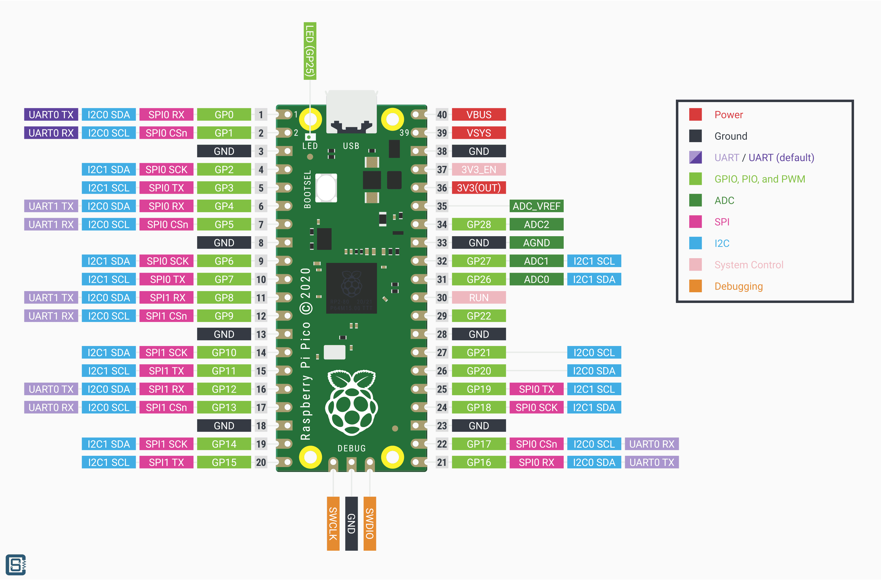
Following the grblHAL software mapping for the firmware 6) we deduce the following map to actual pinouts:
| GRBL Function | Pico GP Pin |
|---|---|
| Step Output X | 2 |
| Step Output Y | 3 |
| Step Output Z | 4 |
| Direction Output X | 5 |
| Direction Output Y | 6 |
| Direction Output Z | 7 |
| Steppers Enable | 8 |
| Limit X | 9 |
| Limit Y | 10 |
| Limit Z | 11 |
Stepper Drivers
There are a few projects for Pico specific shields, however they are costly to get hold of and the Arduino community has very low cost and mature products that is compatible, or at least I believe it is and will explore this and test it for this purpose.
I will explore the CNC Shield that is discussed in detail here 7)
As an alternative we explored TB6600. 8)9)10) These units are very low cost and available on Amazon.
The different models of these types of units are tabled below for comparison.
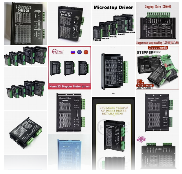
| Feature/Driver | TB6600 | DM556 | DM556T | DM542 | ERP60 | DM860H | DM860S | DM860T |
|---|---|---|---|---|---|---|---|---|
| Input Voltage | 9-42V | 20-50V | 20-50V | 20-50V | 20-50V | 20-50V | 20-50V | 20-50V |
| Output Current | 0.5-4A | 0.5-5.6A | 1.8-5.6A | 1.8-5.6A | 1.8-5.6A | 1.8-5.6A | 1.8-5.6A | 1.8-5.6A |
| Microsteps | 1, 2/A, 2/B, 4, 8, 16, 32 | 1, 2, 4, 8, 16, 32 | 1, 2, 4, 8, 16, 32 | 1, 2, 4, 8, 16, 32 | 1, 2, 4, 8, 16, 32 | 1, 2, 4, 8, 16, 32 | 1, 2, 4, 8, 16, 32 | 1, 2, 4, 8, 16, 32 |
| Control Interface | Digital | Digital | Digital | Digital | Digital | Digital | Digital | Digital |
| Protection Features | Overcurrent, Overheat | Overcurrent, Overheat | Overcurrent, Overheat | Overcurrent, Overheat | Overcurrent, Overheat | Overcurrent, Overheat | Overcurrent, Overheat | Overcurrent, Overheat |
| Applications | General use, CNC machines | General use, CNC machines | General use, CNC machines | General use, CNC machines | General use, CNC machines | General use, CNC machines | General use, CNC machines | General use, CNC machines |
The other option is smaller packaged driver like these:
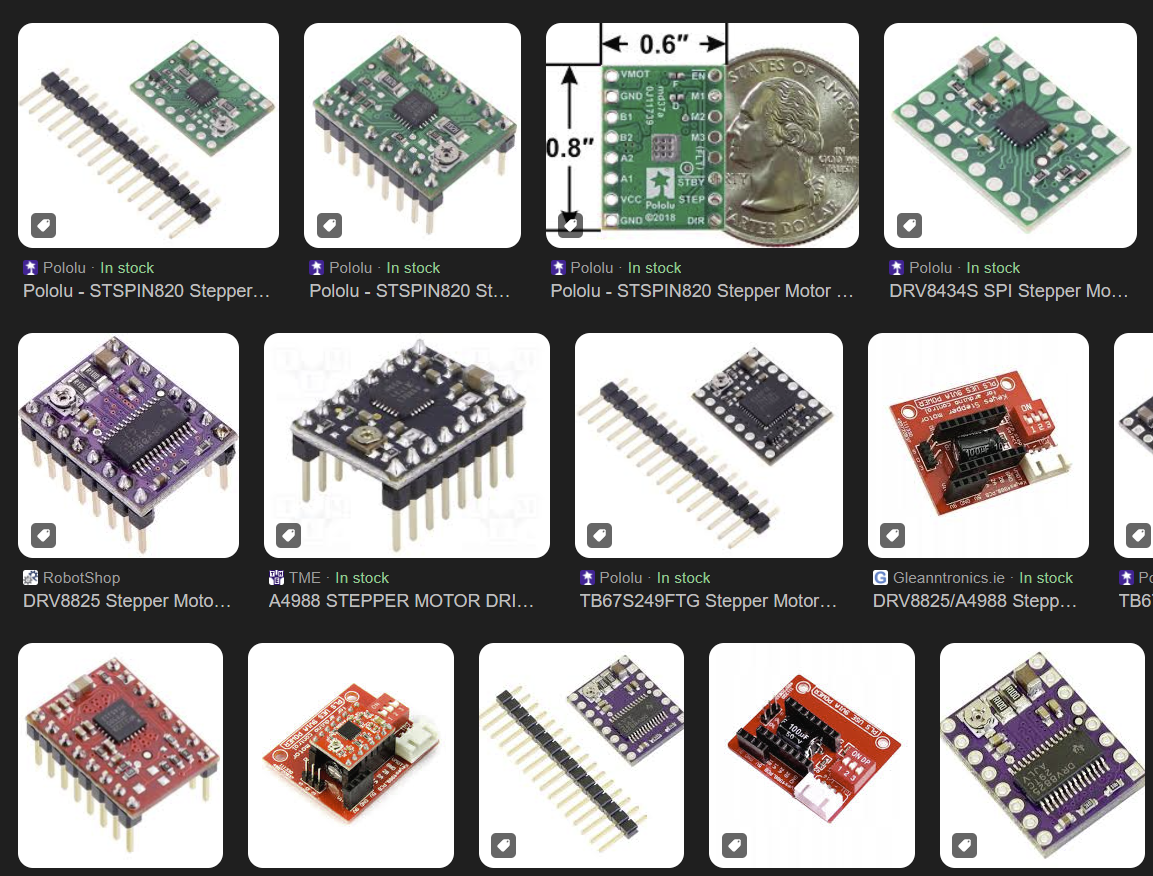
| Feature/Driver | STSPIN820 | DRV8834 | A4988 | MP6500 | A5984 | TB67S249 | DRV8434 | TMCM-1260 |
|---|---|---|---|---|---|---|---|---|
| Operating Voltage | 7-45V | 2.5-10.8V | 8-35V | 8-40V | 8-40V | 8-40V | 8-40V | 8-40V |
| Max Output Current | 1.5 Arms | 1.5 A | 2 A | 2.5 A | 2.5 A | 2.5 A | 2.5 A | 2.5 A |
| Microstepping | Up to 1/256 | Up to 1/32 | Up to 1/16 | Up to 1/16 | Up to 1/16 | Up to 1/16 | Up to 1/16 | Up to 1/16 |
| Protection Features | Overcurrent, Overtemperature, Short-circuit, Undervoltage lockout, Thermal shutdown | Overcurrent, Short-circuit, Undervoltage lockout, Overtemperature, Low-power sleep mode | Overcurrent, Short-circuit, Thermal shutdown | Overcurrent, Short-circuit, Thermal shutdown | Overcurrent, Short-circuit, Thermal shutdown | Overcurrent, Short-circuit, Thermal shutdown | Overcurrent, Short-circuit, Thermal shutdown | Overcurrent, Short-circuit, Thermal shutdown |
| Package Type | QFN 4×4 mm | HTSSOP/VQFN 24-pin | DIP-16 | DIP-16 | DIP-16 | DIP-16 | DIP-16 | DIP-16 |
| Applications | 3D printers, Medical equipment, Industrial printers, Robotics | Toys, Printers, Cameras, Robotics | 3D printers, CNC machines, Robotics | 3D printers, CNC machines, Robotics | 3D printers, CNC machines, Robotics | 3D printers, CNC machines, Robotics | 3D printers, CNC machines, Robotics | 3D printers, CNC machines, Robotics |
The TMC2208 and TMC2209 are known for their silent operation due to their StealthChop technology.
The final choice of driver came down to cost and effort to implement. At the time of writing TB6600 units were available from amazon for €11,10. With optical insulated inputs11) and the cost, it's a no brainer choice for me.
Wiring
The pico datasheet12) section 2.1 confirms use of the 3.3V output for signal purposes of up to 300mA. The TB6600 datasheet13) confirms 15mA currents required to drive the optocouplers.
The proposed microcontroller wiring from the same datasheet proposes the following:
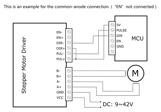
So in keeping with the proposed vendor Microcontroller wiring we then add the enable lines back in and it should look like this.
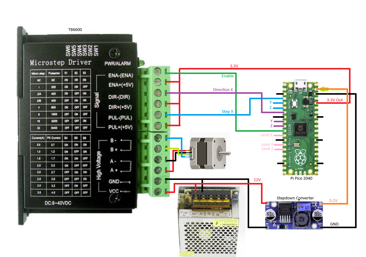
This schematic show the wiring for the X axis, the two Y axis connections for direction and step should be used instead.
These drivers are easy to use and integrate but ended up to be very noisy, the sand table is supposed to be zen, the noise is too distracting.
Alternative Stepper Driver
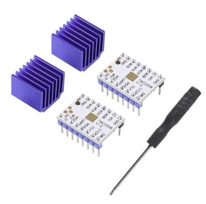
 So some further research had some reasonably costed silent steppers and I opted for some TMC220814) drivers from Amazon and tested then out. I got two for around €9.00, and wired up a motor to a pico 2040 and proceeded to do some tests.
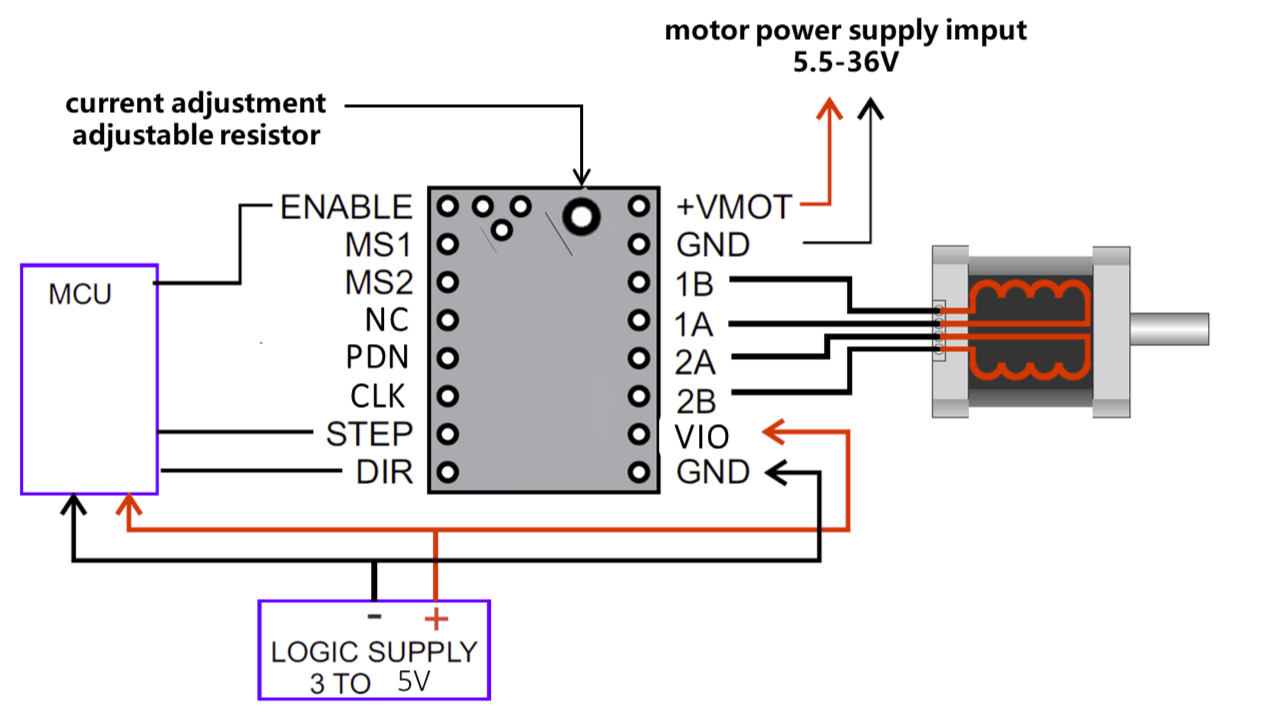
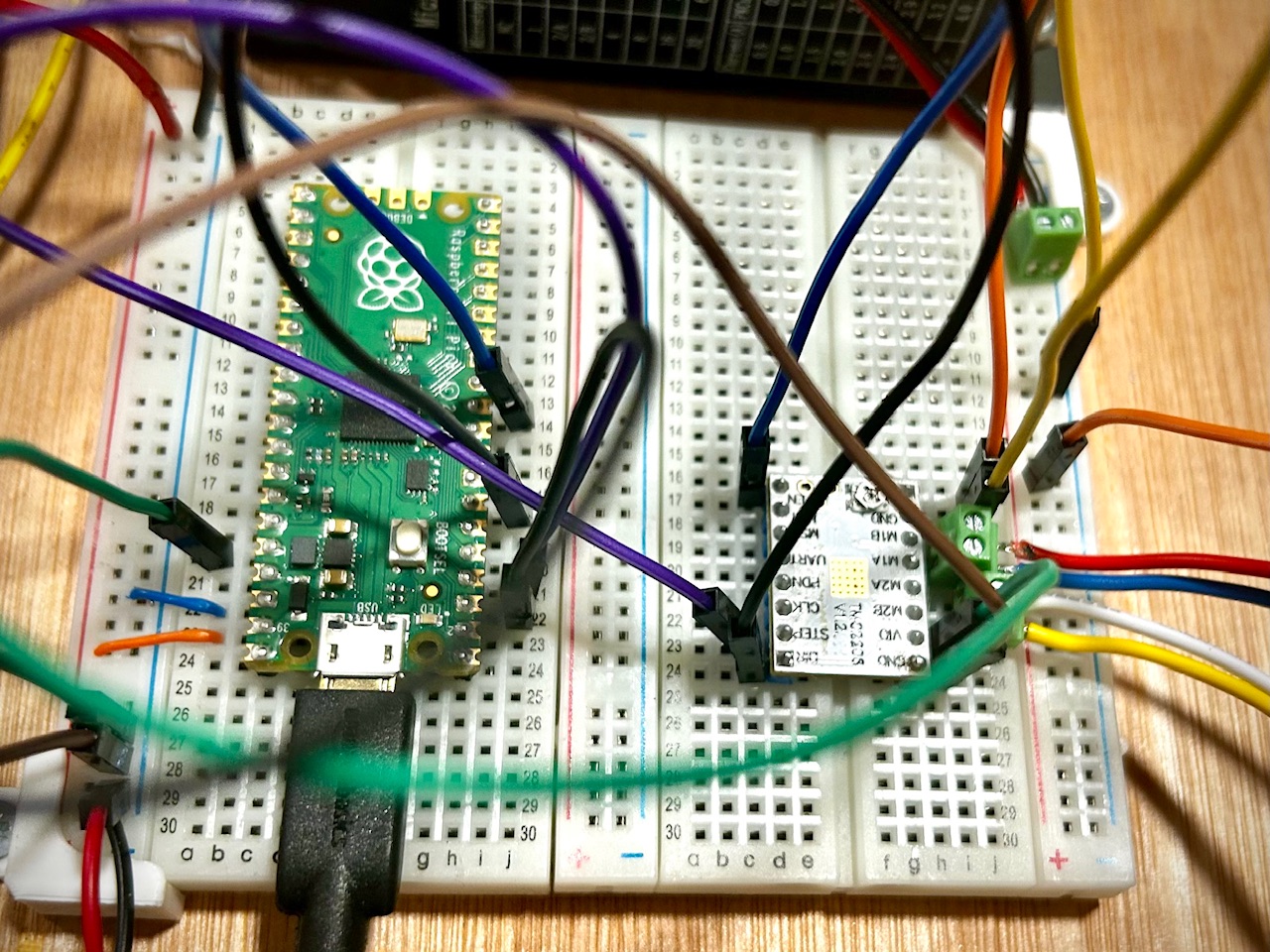 I followed this basic circuit diagram I found online, and the noise reduction was substantial. After some further research I was unable to find a good and cost effective solution to connect mi Pico 2040 to a driver board and explored pcbway that claimed to be low cost custom pcb provider, this proofed to be true and after one steep learning curve and countless hours later I have used the free version of Fusion 360 to create a double layer PC board.
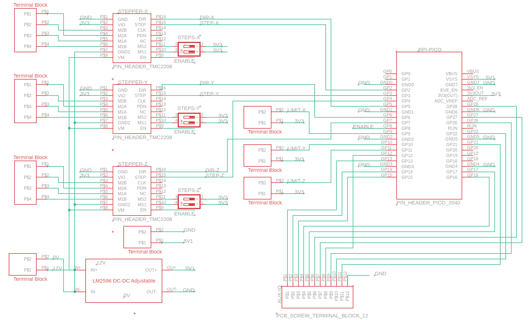
I only need two drivers for the project but decided to make provision for three motors for future projects and also break out all the other IO.
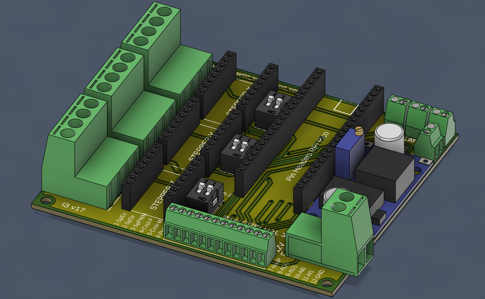
The final design include PCB headers for the pico and all the drives with pluggable terminal connectors for the motors and screw terminals for expansions. The board also includes an adjustable step down regulator for 5v power for the Pico.
The Gerber files for the board is here: linea_rail_controller_schematic_i3_v19_2025-01-20.zip Upload them to PCBWay to get a board manufactured.
The Amazon parts list is here: Amazon Parts List
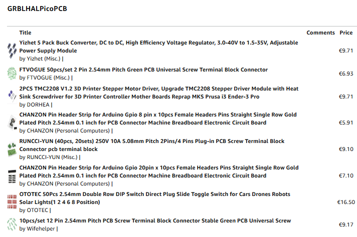
It's working out around €16 per PCB for 5 PCB's and all the parts, then a minimum of €5 to land a Pico 2040 outside the UK, the costs are around €21, if you can buy a populated board for less, it's probably worth avoiding the hassle of sourcing parts, soldering etc. So a populated programmed board will have to sell for €42 plus shipping costs.
GRBL Board Assembly and Setup
Before inserting the microcontroller and drivers into the board, fist set the step down regulator to 5.1V, failing to do so will fry the Pico board.
The DIP switches on the board nex to the stepper is wired to VIO, so to set Micro-stepping simply turn them on or off using this table.
| MS2(-) | MS1(-) | Steps(-) | Interpolation(-) | Mode(-) |
|---|---|---|---|---|
| GND | VIO | 1⁄2 | 1⁄256 | stealthChop2 |
| VIO | GND | 1⁄4 | 1⁄256 | stealthChop2 |
| GND | GND | 1⁄8 | 1⁄256 | stealthChop2 |
| VIO | VIO | 1⁄16 | 1⁄256 | stealthChop2 |

Linear Hardware
Stepper Motors
My stepper motor choice is from what I already have on hand, is popular and abundantly available. Any Nema 17 motor will suffice.
| Brand | Creality 3D 42-40 |
|---|---|
| Item Name | RepRap 42 Stepper Motor |
| Article number | 42-40 |
| SKU | 3204120126 |
| Step angle | 1.8degrees |
| Rated voltage | 4.83V |
| Current rating | 1.5(A) |
| Rated speed | 1-1000(rpm) |
| Rated torque | 0.4(NM) |
| Ambient temperature | -20 ℃ ~ + 50℃ |
| Length | 40mm |
| Application | 3D printer |
| Shaft | Round shaft |
Using this stepper in conjunction with a TB6600, simply set the current limit to match that of the motor selected, regardless pf the voltage supplied to the controller. The controller regulates the current limit set up from the dip switches. 15)
Linear Stage
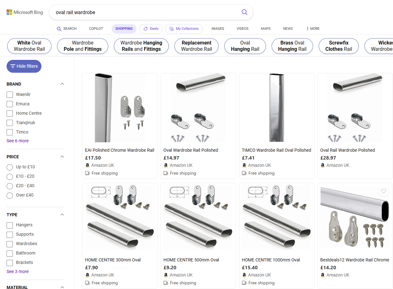
For my linear stage I decided to venture off the well travelled path and investigate alternative rail options.
Browsing at my local hardware store I found polished oval rails like these and started working of a 3D printed design that can use cheap 3D printed options to turn these into a linear stage.
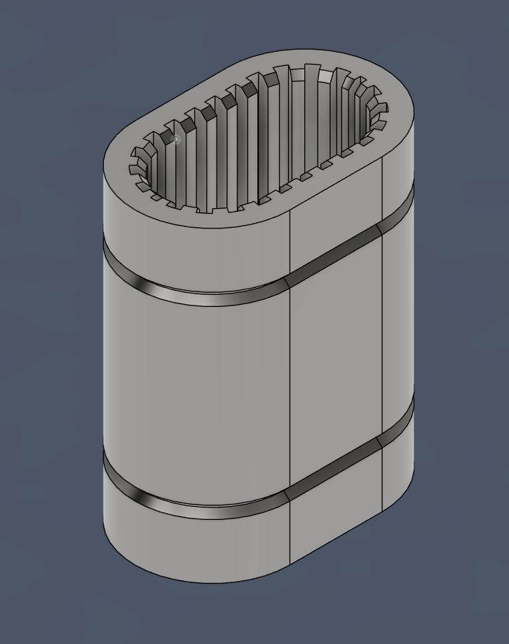 I created some oval shaped linear bearings for starters and testing them on the rails.
The were designed with very tight fit tolerances.
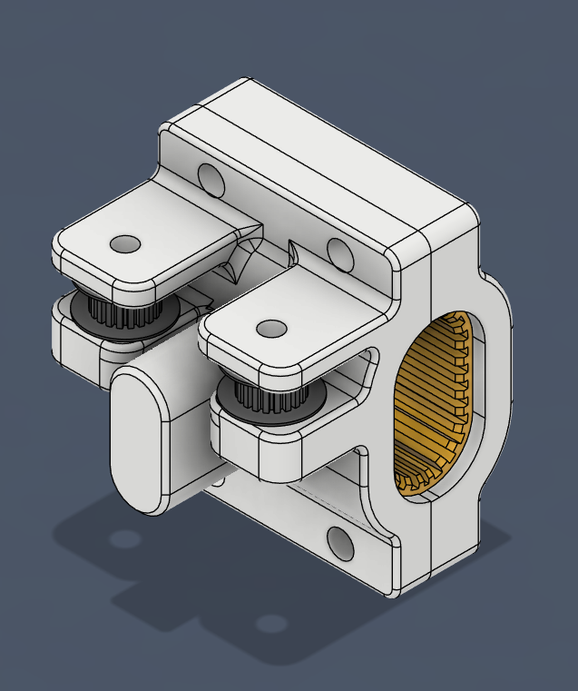
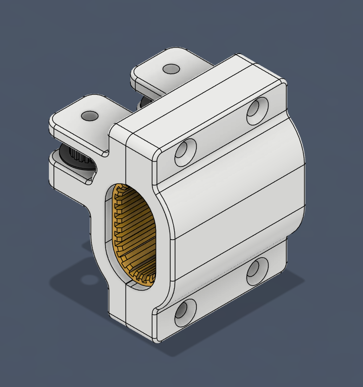 Then created some bearing holders with idler pulley holders and mounts for the cross bar.
The cross bar fit was also tight and I used a mallet to drive it on to avoid play. I realised I did not fit the bearing and designed a split bearing.
The bearings are here: https://www.printables.com/model/1108249-oval-tube-linear-bearing-15x30x50mm
The gantry sliders with bearing and idler pulleys are here: https://www.printables.com/model/1111593-oval-profile-linear-stage-single-bearing
These conceptual designs performed well enough in my initial trails, they will not work well in a 3D print design where sub millimetre tolerances are require, but is worth trying out on simpler applications will lower tolerance requirements.
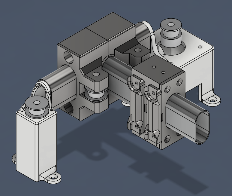 The final design for the core-xy linear stage is here: https://www.printables.com/model/1143004-budget-core-xy-linear-rail-system. The print layout file includes a mirrored layout of the left stage stepper and idler holders.
04_projects/02_kinetic_sand_table.txt · Last modified: by jattie