Table of Contents
| 3D PRINTING AND DESIGN REFERENCE DOCUMENT |
|
|---|---|
| Document Title: | Designing and 3D printing a working pendulum clock |
| Document No.: | 1721211528 |
| Author(s): | jattie |
| Contributor(s): | |
REVISION HISTORY
| Revision | Details of Modification(s) | Reason for modification | Date | By |
|---|---|---|---|---|
| 0 | Draft release | Document the design of a 3D printable clock | 2024/07/17 10:18 | jattie |
Pendulum Clock Design
This document is not completed yet, it is a work in progress with updates added as the build process progresses.
The first part of the document discusses the design process and the second part the build process.
Background
I saw some working 3D printed clocks and became fascinated with the idea and history of clock making. There are multiple publications of makes and 3D designs out there that can be downloaded and assembled, but they all lack the details that I wanted to understand and these are not described in the detail that I needed to understand. Also the terminology in horology literature is unfamiliar and not always clear.
So the aim here is to document my discovery journey for like minded individuals who want to follow this same path to design their own working clocks.
- A timing mechanism using a pendulum
- A geartrain with the right ratios for 60 minutes and 12 hours
- Both minute and hour shafts on the same axis to drive hour and minute hands
- A friction clutch between the gear and hands that allows the time to be set and adjusted
- An hour gear after the clutch to allow setting the time
- A weighted driving mechanism with rewind capabilities, i.e. a ratchet
I read entire books full of math and gear calculations without getting clear indications or drawings on how a practical friction clutch work or how to make one, or how to calculate and design a gear train and get the math to stack up but also then to get the gears aligned on one axis to indicate 60 minutes on the dial or 12 hours on the dial. This wiki page aims to address all of that in clear detail.
The Pendulum
 Some key concepts are actually hidden in the image generated by the escapement design web page. There is an angle between the pendulum position and the centre lines of 2.5 degrees. In that lies the assumption that is also incorporated in the escapement and escapement teeth design and lengths. The escapement arm on the right is just about to be kicked slightly before letting the tooth on the left slip. The weight then needs to be balanced in a way that the power available created by the weight is sufficient to kick the pendulum and maintain the swing and the functioning of the escapement. The design is therefore around a total pendulum swing back and forth of 5 degrees.
The 30 teeth in the design and a five degree pendulum swing at a distance of 980mm will roughly results in a 2 second cycle, so roughly swing back and forth in 2 second and with 30 teeth complete one rotation in 60 seconds. The seconds then needs to be fine tuned by an adjustment mechanism moving the weight slightly up of down.
 The pendulum weight design is 100mm in diameter and hollow and filled with sand to create the weight. The design linked here fully filled is about 140g.
The Escapement
The theory and history of escapements is very clearly described in the freely available publication, The Modern Clock by the author Ward L. Goodrich 1) The most reliable and probably easiest escapement to design and print in the Graham or “dead beat” escapement 2). I started to follow the chapter and then discovered a shortcut to a web source that generates an escapement for you based on the input criteria. 3)
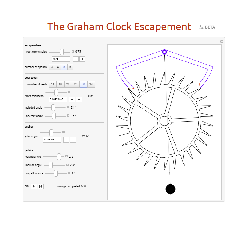
One of the important little details that I initially missed here is the 2.5degree angle of the escapement in the image related to the pendulum mounting angle. My first iteration I mounted the pendulum at right angles where it should be offset to the right at 2.5 degrees.
Design criteria
- 30 tooth gear
- 50 mm outer diameter
- 0.5 mm edge on the tooth so it is printable with 0.4mm nozzle
A one metre pendulum has a two second swing back and forth so I wanted a 30 tooth escapement gear. Through trail and error I discovered that if the gear tip is too thin it just doesn't print and the gear is too small.


Everything you draw is not necessarily printable. Draw and design with the printers capabilities and configuration in mind. A 0.4mm nozzle can not print details smaller than 0.4mm. Dimensions smaller than 0.4mm will not be printed.
So once you have the escapement profile generated I simply take a screenshot, import that as a canvas into Fusion 360 and draw the escapement and gear by tracing over the design generated on the screen.

The drawing then derived from my tweaked design look like this and the latest 3D printable model can be found here: https://www.printables.com/model/936249-50mm-pendulum-clock-escapement
Designing the gear train
At this part into the project I realised how amazing clocks are and all the thought and design that went into them. It is astounding to read about the history of clocks and humbling to read that the history goes back almost 400 years now. 4)
The fist choice to make was pitch and I decided to go with 1.5mm and did a test print to see what the meshing, accuracy and quality looks like. I also wanted the clockwork o be reasonable in size, so tried to keep my gears manageable.

Combining whiteboard designs and sketching using fusion I managed to figure out a layout and some ratios that can work.
| Name | Gear | Pinion | Ratio | Seconds/rev | Comments |
|---|---|---|---|---|---|
| 1. Esc | 30 | 8 | - | 60s | The escapement with a 8 teethh pinion |
| 2. Int1 | 60 | 8 | 7.5 | 450s | Intermediate gear, ratio is 60teet /8teeh from previous pinion |
| 3. Min | 64 | 15 | 8.0 | 3,600s | 1 hour - so the minute hand take one hour to complete the rotation |
| 4. Int2 | 60 | 20 | 4.0 | 14,400 | 4 hours |
| 5. Hour | 60 | - | 3.0 | 43,200 | 12 hours |
The ratios is calculated using the gear teeth in the same row divided by the pinion teeth in the previous row. Then ratio 2 and 3 combined is 7,5 x 8 = 60 and the combined ration for gear4 and 5 is 4 x 3 = 12
This was not the end of it thou. With this design, I could not get the hour gear and the minute gear on to the same shaft, because the radius of the pinion and the radius of the gear combined needs to be same dimension.
 So then working backwards with the gear pitch5), through trail and error I managed to get to this solution in a straight line.
 Then once the dimensions were determined I simply rotated the entire geartrain into a zig-zag patters with 45 and 90 degree angles, resulting in this compact layout.
I thought I was done here when I stumbled upon another clock design online6) and having now gained a deeper understanding of the gear trains, I immediately recognised what I was looking at.

So using the same numbers for the gears in the table above, you can see the same gearing pattern in the bottom layer, but the hour hand gears are on the minute shaft. I have seen this on exploded views, but not in a layout like above that made sense. So the final iteration will attempt to incorporate this idea, back to the drawing board….
Separate Hour Gear Design
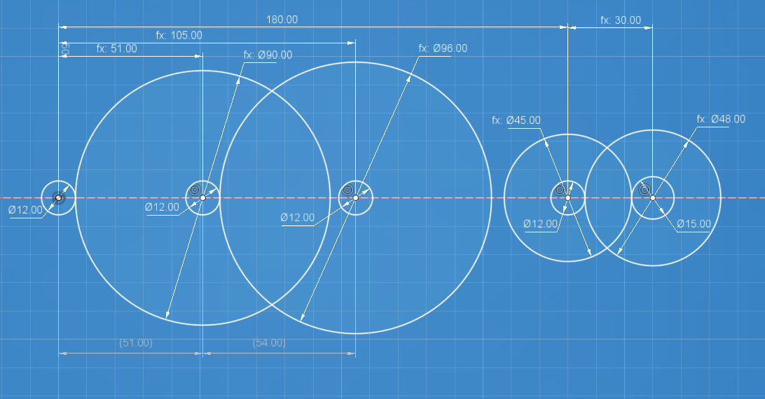
The sketch illustrates the intersection points of the proposed gear pitches.
A gear with a modulus of 1.5mm and 8 teeth will have a pitch of 12mm. This is essentially the point where the gear teeth interact.
So the redesign keep the initial gear configuration for the first three gears and then adds the two hour gears on the right on top of the same shaft driven by the minute gear.
| Gear | Pinion | Ratio | Comment |
|---|---|---|---|
| - | 12(8) | - | |
| 90(60) | 12(8) | 7.5 | |
| 96(64) | 12(8) | 8 | 7.5×8=60 |
| Gear | Pinion | Ratio | Comment |
|---|---|---|---|
| - | 12(8) | - | On the same shaft as the minute gear |
| 48(32) | 15(10) | 4 | driving the 45 gear |
| 45(30) | - | 3 | combined ratio of 4×3=12 |
So this is a coloured view of the entire drive train with the yellow parts being responsible for generating the seconds, green then stepping that down to minutes and delivering the output to a shaft driving the minute hand. The red gears than steps everything down further by a combined ratio of 12 and driving the hour hand. Lastly the blue gears stepping down everything by another ratio of 56.25 to provide enough power for 10 days.
Designing the Friction coupling
The information online is very vague and unclear, and maybe I am just not entering the right criteria, however I was again able to eventually figure this our from another clock projects online7) by carefully reading and looking at the details. To be honest, this is the only place I could find any hint of how to go about designing friction coupling.
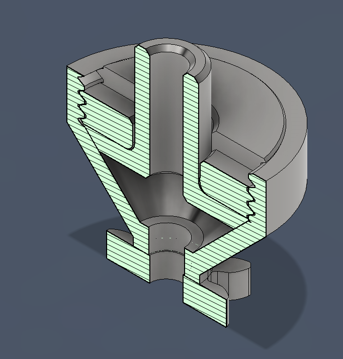
In the section view on the left, right in the middle line where the dials are attached, is the assembled part and to the right the exploded view.
The shaft part is held in place in the gear with the flat surface pressing against a tapered surface and the threaded nut determines the friction required to freely turn this part.
The clutch design is available here on Fusion 360: https://a360.co/3LzTb5z and you can get a printable part here: https://www.printables.com/model/948932-friction-clutch-for-clock
Designing the power source
The ideas needed is encapsulated in this design:
The intension then is to combine this idea with a chain and sprocket arrangements8) to manage the weights.
The final chain wheel design looks like this:
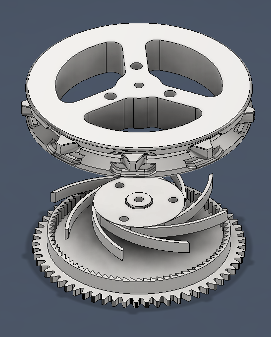
See the design iteration and history here:
The ratchet mechanism facilitates pulling the chain wight back up without stopping the pendulum.
Parts, Printing and Assembly
For this part of the project we are preparing the following:
- Cutting and preparing gear shafts
- Cutting threaded rods to hold plates with spacers.
- Printing plates and spacers
- Fitting Bearings
Preparing the Gear Shafts
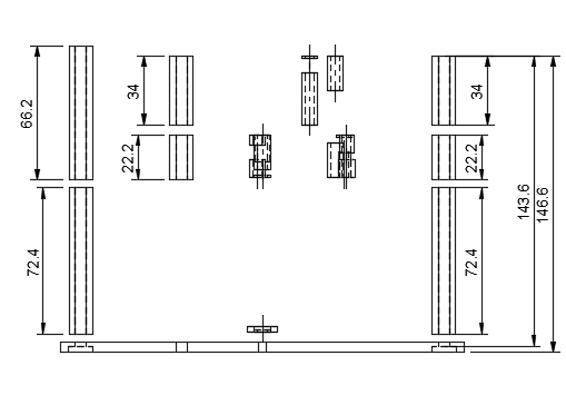
The gear shafts are cut from any 4mm round rod material. I had some 4mm steel wire and searched for 4mm bearings to go with that.
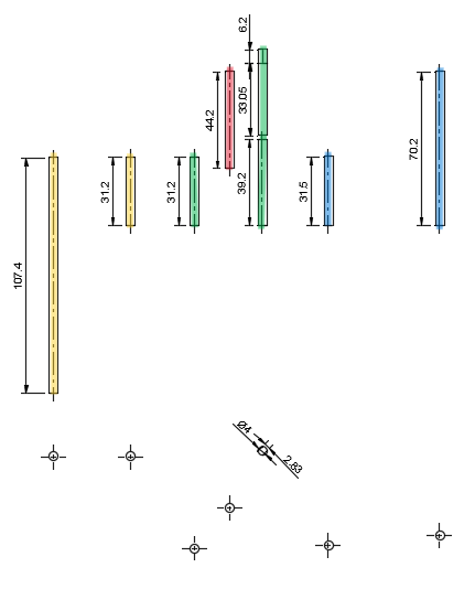
The bearings selected for this project has a 4mm inner diameter, so the shafts to be prepared is 4mm thick and of various lengths as show in the diagram above.
From left to right:
| Shaft Name | Shaft Length |
|---|---|
| Escapement | 107.4mm |
| Escapement Gear | 31.2mm |
| Minite i | 31.2mm |
| Hour i | 44.2mm |
| Minite lower | 39.2mm |
| Minute Upper | 39.25mm |
| Power i | 31.5mm |
| Power | 70.2mm |
So rounded off to working tolerances:
| Dimension | Quantity |
|---|---|
| 107.5mm | x1 |
| 70.2mm | x1 |
| 44.5mm | x1 |
| 39.5mm | x2 |
| 31.5mm | x3 |
Use the list above and prepare the metal shafts to fit into the bearings
Installing gear shafts
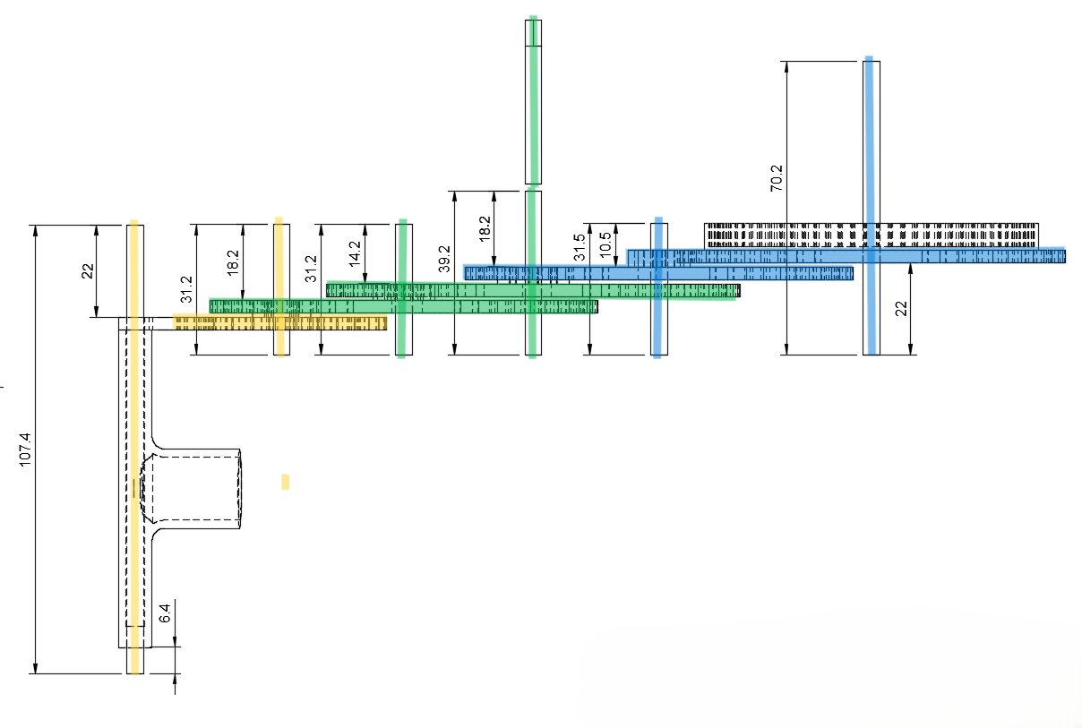
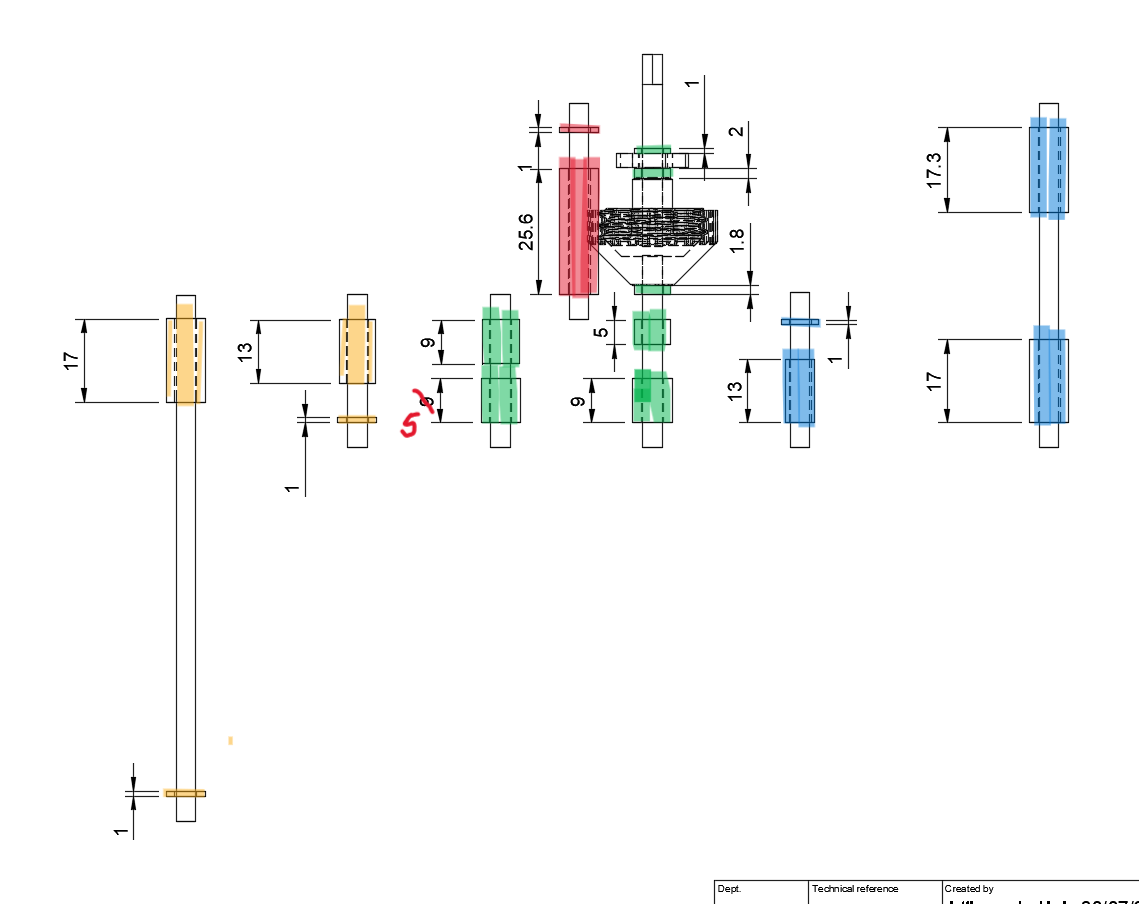
Once the shafts are cut to length and cleaned up, proceed to print the various gear assemblies and install the gear shafts by tapping gently with a hammer on a flat surface with a hole through and measure the shafts for the correct protrusion distances as shown below.
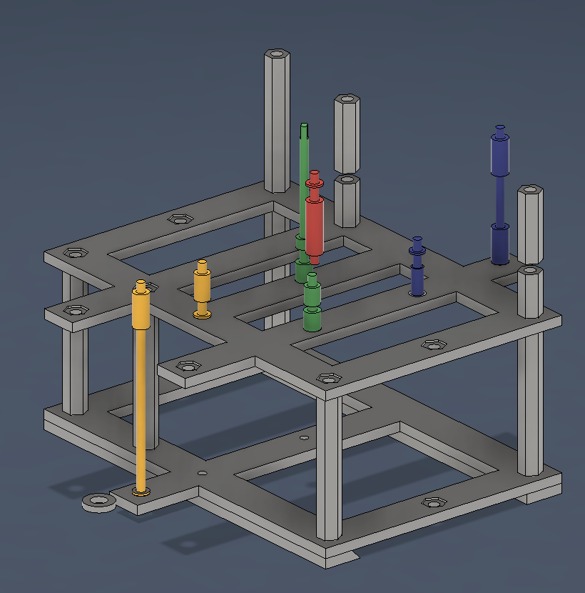
Assembly Rods
We're using a 4mm threaded rod to hold the plates together with plate spacers in between.
