This is an old revision of the document!
| 3D PRINTING AND DESIGN REFERENCE DOCUMENT |
|
|---|---|
| Document Title: | Document Title |
| Document No.: | 1728994779 |
| Author(s): | jattie |
| Contributor(s): | |
REVISION HISTORY
| Revision | Details of Modification(s) | Reason for modification | Date | By |
|---|---|---|---|---|
| 0 | Draft release | Document description here | 2024/10/15 12:19 | jattie |
Multi Colour Designs
This topic came up working on a various projects that required a faceplate, like a clock face, a ruler or the faceplate for a sundial.
CAD Design Approach
The obvious way is to emboss or slice a surface and paint the layers in using slicers. One very elegant solution is to create the parts you want to see as separate objects.
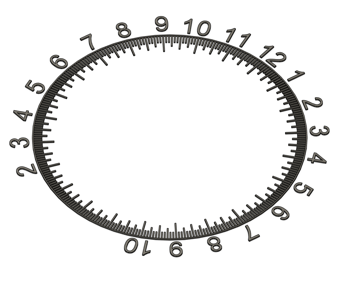
Then create the faceplate on the same layer, extruding downwards to create a thicker body that the parts in step one, for example, the numbers and lines in part one I created is 0.8mm deep, so will be four layers deep with a print height set at 0.2mm. The Faceplate body I extruded to 3mm.
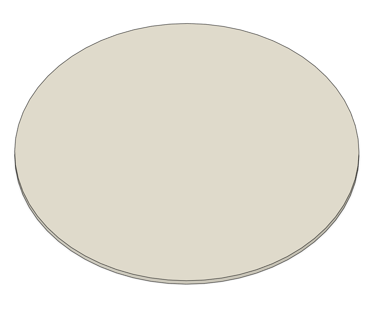
The next step the using the numbers and dial indicators cut the faceplate and keep the parts you're cutting with.
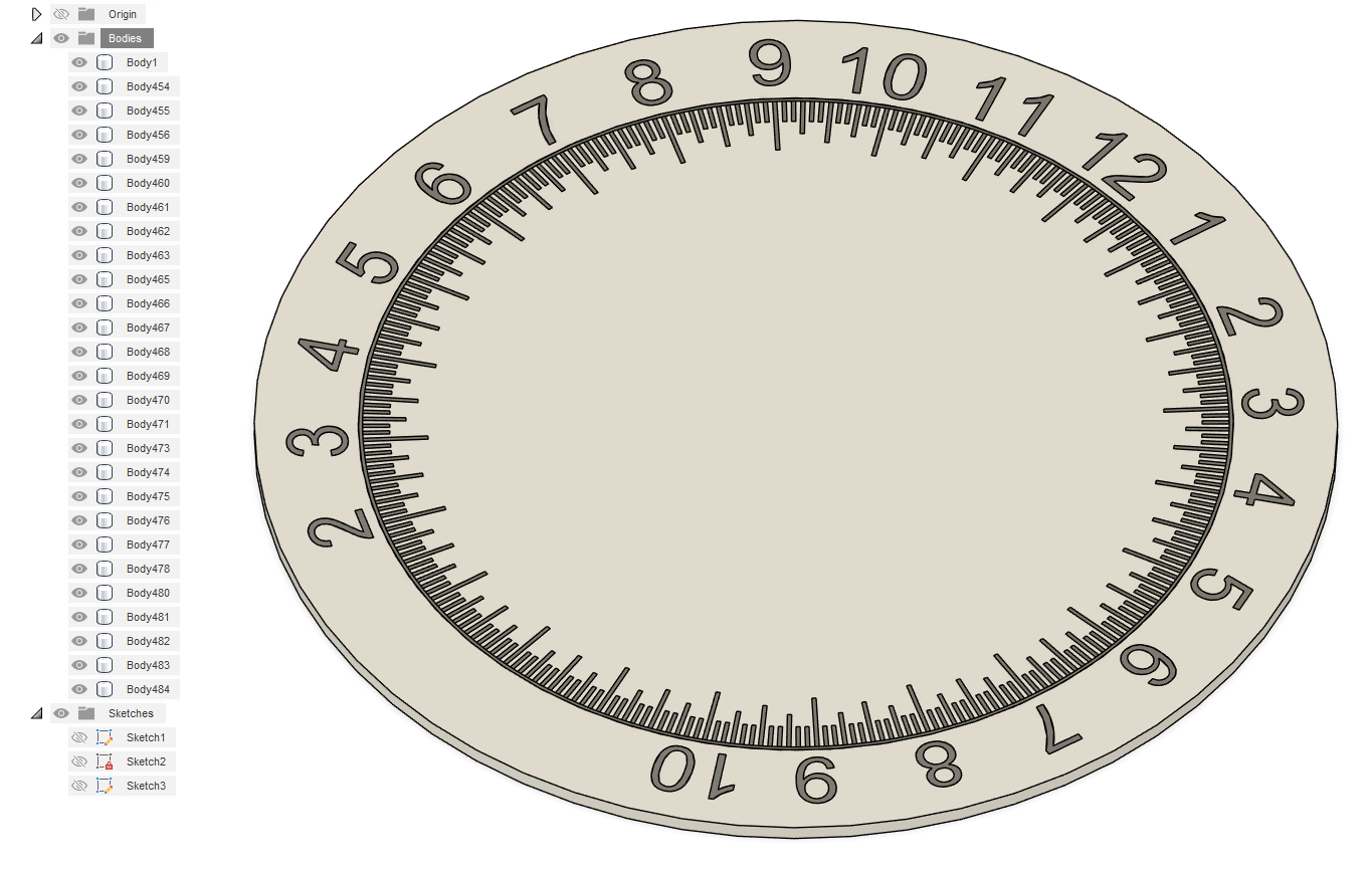
This results in many bodies with letter cut into the faceplate but at the exact same height.
The next step is to export all the parts as one file to use in the slicer.


This is an important step for we need all the parts in the slicer in it's right positions. For Fusion360 the process looks like this. It creates a .stl file that can be slices with all the parts in it's positions.
Slicer Treatment
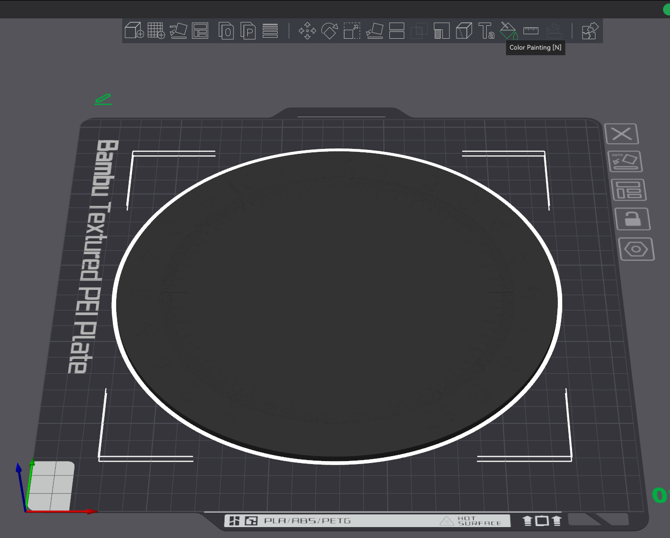
I am using Orca slicer and Bambu Studio. The first step importing it into a slicer it looks like this.
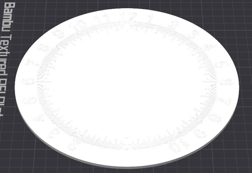
I then change the default filament to black and then proceed to paint in the faceplate white.
